
Time-Resolved Cathodoluminescence
Introduction
Time-resolved cathodoluminescence spectroscopy (TRCL) consists in extending regular CL into the time domain by using a pulsed electron beam instead of a continuous one, as well as using a time-resolved detector synchronised with the pulsed beam to record local luminescence decays from the probed material.
Principles
Luminescence from a material after excitation has a characteristic lifetime that depends on the number and type of carrier recombination pathways that are present in the material. These pathways arise from the presence of states in the electronic band structure and can be broadly categorized as either radiative or non-radiative. For example, near band edge luminescence and shallow impurity dopant-mediated luminescence are two radiative pathways typically found in semiconductors. Crystal defects such as threading dislocations or stacking faults generally give rise to non-radiative recombination. Although they do not result in luminescence themselves, non-radiative pathways do still reduce the luminescence lifetime of the material.
Given enough time, excited carriers will always recombine and relax to their ground state via either radiative or non-radiative pathways, with each pathway exhibiting a characteristic recombination time constant. Generally, the decay time constant for a given excited state τ can be expressed as follows:
1meas=1rad+1nrad
Here τmeas is the measured time constant, representing the overall carrier lifetime, while τrad and τnrad are the radiative and nonradiative recombination rates, respectively.
In real systems, interpretation can become more complex, especially when the material system features two or more states that are close in energy, in which case the contribution to τ for each state has to be taken into account as well as an exchange term between the states, all of which needs to be input into a rate equation. This principle stands for any type of luminescence.
By using pulsed electron beam excitation and time-resolved detectors, TRCL combines high time resolution with the high spatial resolution of cathodoluminescence spectroscopy, enabling unique insight into local variations of carrier recombination lifetimes.
The repetition rate of the system can be critical as the pulse-to-pulse period has to be long enough for the system to fully relax to be able to extract meaningful results from the measurements.
Instrumentation
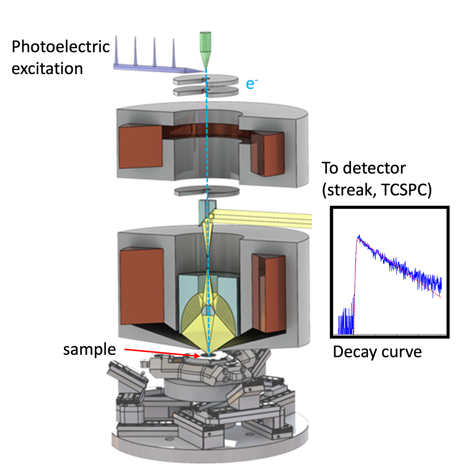
A TRCL setup consists of a regular CL setup, improved with a pulsed electron source, obtained either by blanking the regular electron source, or by using the photoelectric effect to trigger electron emission on the existing tip. The former solution is cheaper and very flexible in terms of repetition rate, while the latter one yields better time and spatial resolutions, as well as better fine tuning of the electron dose.
On the detection side, appropriate detectors, such as a time-correlated single photon counting (TCSPC) electronics together with a single photon counting point detector or a streak camera, are needed in order to be capable of recording time traces. The former therefore outputs 1D luminescence decay lines. The latter outputs 2D maps with the time delay on one axis and wavelength on the other. This is therefore the preferred solution when dealing with complex systems containing several energetically-close states with different recombination properties. TCSPC-based solutions are, however, much more flexible in terms of detection wavelength sensitivity and repetition rate flexibility.
Example results
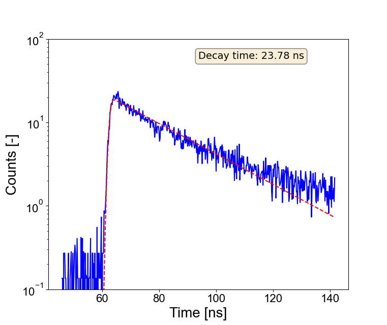
Figure 2 shows a typical decay measured using time correlated single photon counting electronics. In this case, a 10 nm spectral band has been integrated around the NV0 vacancy center of a nano-diamond. TRCL in this case allows for the measurement of exciton lifetimes in a single nano-diamond. Figure 3 features a streak map obtained on the near band edge emission peak of a GaN sample. The added complexity of streak results compared to TCSPC allows
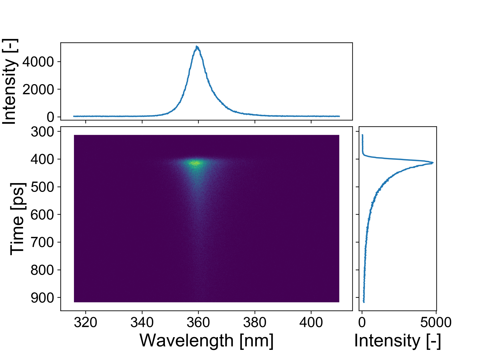
highlighting of inter-state transitions when they happen, where the rise and fall time of a state can be linked to those of another state.
Benefits and Further Reading
TRCL allows for the following applications, among others:
- Dopant concentration measurement in boron-doped diamond [1]
- Highlighting strain induced exciton drift in ZnO nanowires [2]
- Precise dose control for samples highly sensitive to beam damage [3]
- Mapping the spread of exciton quenching induced by point defects in a wide band gap semiconductor [4]
Latest Scientific Publications
Time-Resolved Cathodoluminescence
CL from beam-sensitive optoelectronic materials - hybrid halide perovskites
Explore our high-resolution cathodoluminescence tools designed for superior materials characterization.


